Qc012 Camera App |top|
Communicate through the camera using a built-in microphone and speaker. Smart Tracking & AI:
The QC012 Camera App has received positive reviews from users, who praise its ease of use, feature-rich interface, and high-quality output. Many users have reported that the app has helped them to take better photos and videos using their smartphone cameras.
: The primary meaning of QC012 is a hardware platform used for Wi-Fi security cameras. These are often manufactured by various companies (like ACSVision) and sold under different brand names. A common example is the ACSVision QC012 , a generic IP camera supporting industry-standard protocols like ONVIF and RTSP for seamless integration with other systems. qc012 camera app
: If the camera was previously used, press and hold the Reset button (usually located near the SD card slot) for about 5 seconds until you hear an audible tone. App Setup :
Scan the QR code printed on the camera hardware or choose it from the scanned list. Communicate through the camera using a built-in microphone
Plug your qc012 camera into a power source. Wait for it to complete its startup sequence, which may be indicated by a light pattern or a voice prompt.
To get the most out of the QC012 camera app, you must configure it to match your device hardware capabilities. Follow these steps for an optimal baseline configuration. 1. Granting Necessary Permissions : The primary meaning of QC012 is a
Upon launching the app for the first time, your mobile operating system will prompt you for several permissions. Granting these is critical for core functionality:
: A versatile option for managing multiple brands of cameras on a single dashboard. Connection Guide To set up your camera, follow these general steps:
eFatigue gives you everything you need to perform state-of-the-art fatigue analysis over the web. Click here to learn more about eFatigue.
Qc012 Camera App |top|
Welds may be analyzed with any fatigue method, stress-life, strain-life or crack growth. Use of these methods is difficult because of the inherent uncertainties in a welded joint. For example, what is the local stress concentration factor for a weld where the local weld toe radius is not known? Similarly, what are the material properties of the heat affected zone where the crack will eventually nucleate. One way to overcome these limitations is to test welded joints rather than traditional material specimens and use this information for the safe design of a welded structure.
One of the most comprehensive sources for designing welded structures is the Brittish Standard Fatigue Design and Assessment of Steel Structures BS7608 : 1993. It provides standard SN curves for welds.
Weld Classifications
For purposes of evaluating fatigue, weld joints are divided into several classes. The classification of a weld joint depends on:
- the macroscopic geometry of the pieces welded,
- the direction of the cyclic stresses, and
- the location of the crack that leads to failure.
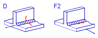
Two fillet welds are shown below. One is loaded parallel to the weld toe ( Class D ) and the other loaded perpendicular to the weld toe ( Class F2 ).
It is then assumed that any complex weld geometry can be described by one of the standard classifications.
Material Properties
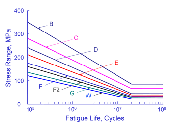
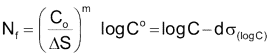
The curves shown above are valid for structural steel welds. Fatigue lives are not dependant on either the material or the applied mean stress. Welds are known to contain small cracks from the welding process. As a result, the majority of the fatigue life is spent in growing these small cracks. Fatigue lives are not dependant on material because all structural steels have about the same crack growth rate. The crack growth rate in aluminum is about ten times faster than steel and aluminum welds have much lower fatigue resistance. Welding produces residual stresses at or near the yield strength of the material. The as welded condition results in the worst possible residual or mean stress and an external mean stress will not increase the weld toe stresses because of plastic deformation. Fatigue lives are computed from a simple power function.

The constant C is the intercept at 1 cycle and is tabulated in the standard. This constant is much larger than the ultimate strength of the material.
The standard is only valid for fatigue lives in excess of 105 cycles and limits the stress to 80% of the yield strength. Experience has shown that the SN curves provide reasonable estimates for higher stress levels and shorter lives. In eFatigue, the maximum stress range permitted is limited by the ultimate strength of the material for all weld classes.
Design Criteria
Test data for welded members has considerable scatter as shown below for butt and fillet welds.
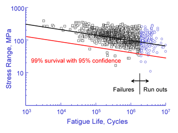
Some of this scatter is reduced with the classification system that accounts for differences between the various joint details. The standard give the standard deviation of the various weld classification SN curves.
The design criteria d is used to determine the probability of failure and is the number of standard deviations away from the mean. For example d = 2 corresponds to a 2.3% probability of failure and d = 3 corresponds to a probability of failure of 0.14%.
TryMirror © 2026